|
Especially in the pre war years, the differences between civilian and
military 16H motorcycles were not very distinct.
The present abundance of "pre-war"
civil 16H look alike motorcycles makes it clear that the details are not
very known to most people.
Through the investigation of two "proven to be authentic" pre war
civilian 16H machines (one from 1935 and one from 1937), I have been
able to at least corroborate
the claim that the military motorcycles did indeed have an increased
ground clearance. Through measuring and comparing a number of frame
dimensions, it can be clearly determined which is a military or trails
frame and what is a genuine civilian machine.
Both front down tube and saddle tube of the military bike are shorter
than those of the civilian machines, thus lifting the engine higher from
the ground. Other frame dimensions are basically the same.
The
claim as made in many books
on the WD16H having "stronger front fork springs" has been
found to be incorrect. According to the Norton Assembly books, only 25%
stronger Rebound springs were applied, not stronger Front Fork springs.
These stronger Rebound springs were subsequently also used for the
civilian machines.
All spare parts lists
that I have give the same part numbers, from 1937 to 1945. The military
Big 4 did indeed have stronger Front Fork spring, which is clear from the
different part number of it.
Below a
list giving a number of details differences between civil and military
bikes between 1936 and 1946. This is not definitive and probably not
complete but based on the
best information available to me at the moment. (With great help from
Richard Payne, Belgium, Timothy Walker and Roger Deadman in England).
Norton Model years went from October to October so that e.g.
enclosed valves (1938) engines were built and sold starting in the last months
of 1937!
At the bottom some details of military
origine.
|
PART |
1936 |
1937 |
1938 |
1939 |
1940 -1945 |
1946 |
|
Solid "adjustable" handlebar clamps |
M |
M |
M |
M |
M |
- |
|
Rubber cushioned handlebar
clamp introduced in 1935 |
C |
C |
C |
C |
- |
C |
|
1 inch handlebars |
M C |
M |
M |
M |
M*12 |
? |
|
7/8th inch handlebar |
- |
C |
C |
C |
M*12 |
? |
|
Open valve cover
|
M C |
M C |
M |
M |
M |
- |
|
Enclosed valves |
- |
- |
M*1 C |
M*1 C |
- |
C |
|
Oil tell tale |
M C |
M C |
M |
M |
M |
- |
|
No oil tell tale |
- |
- |
M*1 C |
M*1 C |
- |
C |
|
Front brake plate/drum left hand
side *2 |
M C |
M C |
M C |
M |
M |
- |
|
Front brake plate/drum right hand
side *2 |
- |
- |
- |
C |
- |
C *3 |
|
Saddle spring studs vertical |
M C |
M |
M |
M |
M |
- |
|
Saddle spring studs
horizontal |
- |
C |
M*11 C |
M*11 C |
- |
C |
|
Gear position indicator
small |
M C |
M C |
M C |
M C |
- |
|
|
Gear position indicator
large |
- |
- |
- |
- |
M |
|
|
Gear change lever straight *14 |
M C |
MC |
- |
- |
- |
|
|
Gear change lever hooked down *14 |
- |
- |
MC |
MC |
MC |
C |
|
Dolls head gear change mechanism |
MC |
MC |
MC |
MC |
MC |
- |
|
Enclosed gear change mechanism |
- |
- |
- |
- |
- |
C |
|
Nut front fork shock
absorber |
M |
M |
M |
M |
M |
|
|
Handwheel front fork shock
absorber |
C |
C |
C |
C |
- |
C |
|
Footrest tubes welded to
engine plates |
M C |
C |
C |
C |
- |
|
|
Footrest tubes
interchangeable |
M*10 |
M |
M |
M |
M |
|
|
Serrated foot hanger long |
C |
C |
C |
C |
- |
|
|
Serrated foot hanger short |
M C*4 |
M C*4 |
M C*4 |
M C*4 |
M |
|
|
Rubber cushioned footrests |
M C |
M C |
M C |
M C |
- |
C |
|
Tubular, steel footrests |
- |
- |
- |
- |
M*5 |
|
|
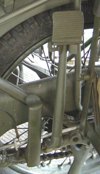
Rear brake pedal short |
C |
C |
C |
C |
- |
|
|
Rear brake pedal long |
M C*6 |
M C*6 |
M C*6 |
M C*6 |
M |
|
|
Side stand |
M |
M |
M |
M |
M |
|
|
Centre stand |
C |
C |
C |
C |
- |
|
|
Semi-loop (diamond) frame |
M C |
M C |
M C |
M C |
M |
|
|
Cradle frame |
- |
- |
- |
- |
- |
C |
|
Petrol tank overhead valve engine cut-out |
C |
C |
C |
C |
- |
C |
|
Petrol tank with only Spark
plug dome |
M |
M |
M |
M |
M |
- |
|
Silencer 1935 model |
M C |
M C |
M |
M C |
M |
C |
|
Silencer 1938 (Cows udder) |
- |
- |
C |
- |
- |
|
|
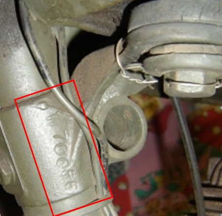
Toolbox narrow (approx 3 1/8") |
M C |
M C |
M C |
C |
- |
C*7 |
|
Toolbox wide (approx 4 1/2") |
- |
- |
- |
M |
M |
- |
|
Tyre inflator under petrol
tank |
M C |
M C |
M C? |
M |
M |
- |
|
Tyre inflator on rear chain
guard |
- |
- |
C? |
C |
- |
C |
|
Additional mudguard stay
between halfway rear upper mudguard stay to rear lower mudguard stay/bottom
portion of mudguard |
M |
M |
M |
M |
M |
|
|
No additional mudguard stay |
C |
C |
C |
C |
- |
C |
|
Single rear numberplate top fixing bolt |
C |
M |
- |
- |
- |
- |
|
Two rear numberplate top fixing bolts |
- |
C |
M C |
M C |
- *13 |
C |
|
Front numberplate |
M C |
M C |
M C |
M C |
- *13 |
C |
|
Pillion foot rest lugs on left
and right lower chain stay short version |
M C |
M C |
M C |
C |
- |
- |
|
Pillion foot rest lugs on left
and right lower chain stay high/long version *8 |
- |
- |
C |
- |
- |
- |
|
Sidestand lug on left rear
chain stay and pillion footrest lug on right rear chain stay and
optional a “bolt-on”
pillion foot rest lug on left rear chain stay |
M |
M |
M |
M |
- |
- |
|
Sidestand and pillion foot
rest lug on
left rear chain stay and pillion foot rest lug on right rear chain stay |
- |
- |
- |
- |
M*9 |
- |
Notes:
*1
Only on non-British Military bikes (NIZAM India contract for instance),
*2 Different front fork to accommodate righthand brake
plate reaction arm,
*3 BSA type headlamp supports
(two strips in V shape on its side), so no lugs for the headlamp “prongs”,
*4 Also used on civil Trials
versions,
*5 Steel tubular footrests
introduced around 1942 to preserve rubber,
*6 To go with short serrated
footrest hangers on civil Trials versions,
*7 In
1946 a completely new design toolbox was introduced,
*8 Longer
pillion footrest lugs required to cater for the "Cows Udder" silencer,
*9 Introduction
of dedicated left hand pillion footrest lug approximately second half of
1940.
*10 Separate footrest tubes and engine plates introduced from
20th August 1936
*11 1938 model WD16H destined for India Stores Dept were
provided with the civilian horizontal studs
*12
First military contract with 7/8th inch "universal" handlebars was
S5161 (1944/45), likely all late MC's had 7/8th.
*13
Front and rear number plates discontinued in 1940
*14 Gear change lever (straight and hooked) clinch bolt fitting
from bottom in combination with small indicator,
top fixing on hooked gear change
levers in combination with the long indicator.
Based on: 1937, 1939, 1940 and 1946 spareparts
lists,
1938 and 1939 Norton Catalogues,
Various years official pictures
1938 to 1945 military motorcycle pictures
|